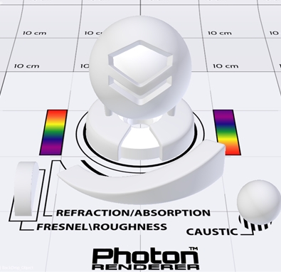
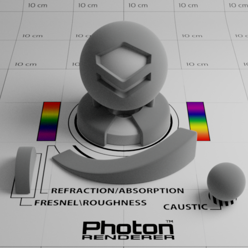
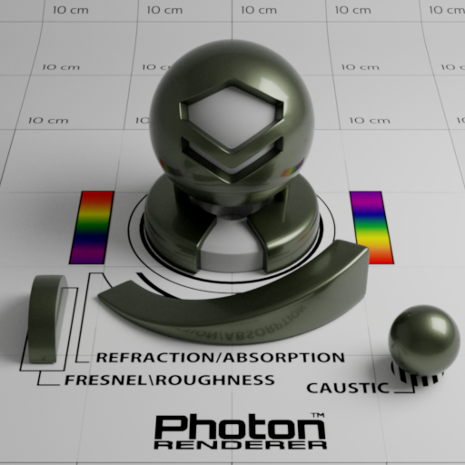
We present material implementations with a fairly professional test scene (we are using CGTrace’s Material Ball made by victorborges. Some part of the model is modified for Photon to use). It is a scene that facilitates observation and comparison of material appearances. There is an inset object within the main model that has a 50% albedo, which serves as a neutral color comparator. The smaller objects at the front is for inspecting basic characteristics (annotated directly on the ground plane) of the material. Two color legends are placed on the sides as a simple color checker. A standard 24-color checker may be better for this purpose (this is left for future work). This scene is lit by a 7-watt white (standard illuminant-E, constant spectrum) rectangular area light on the right.
Matte Opaque
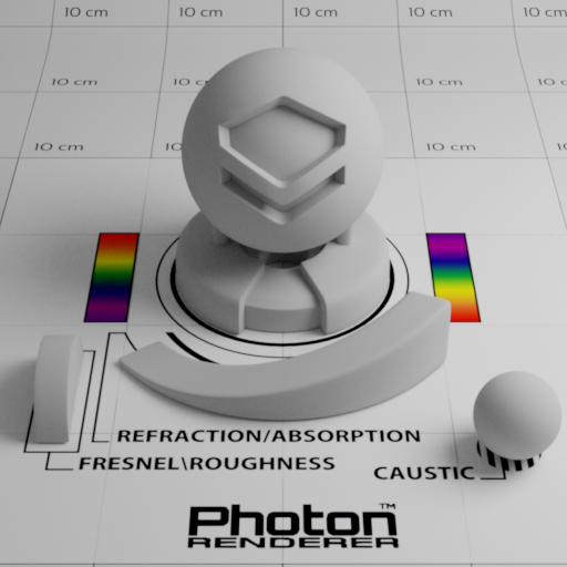
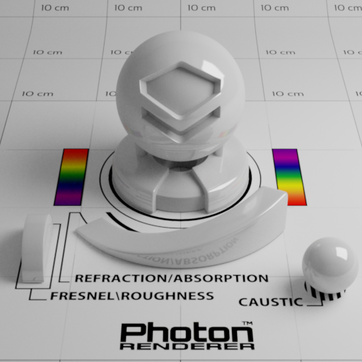
A classic material that is almost present in every renderer, no matter offline or real-time, is Lambertian-based diffuse BRDF. Shown below is a matte surface with albedo being set to 50%.
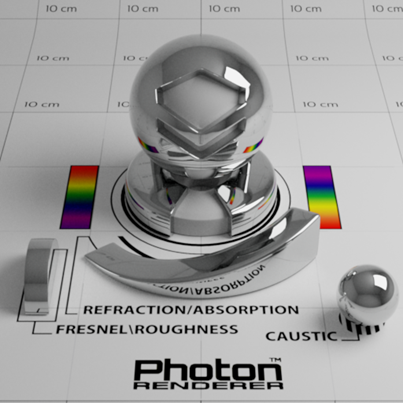
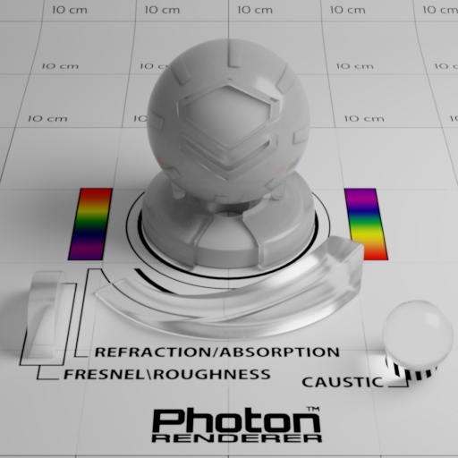
Ideal Substance
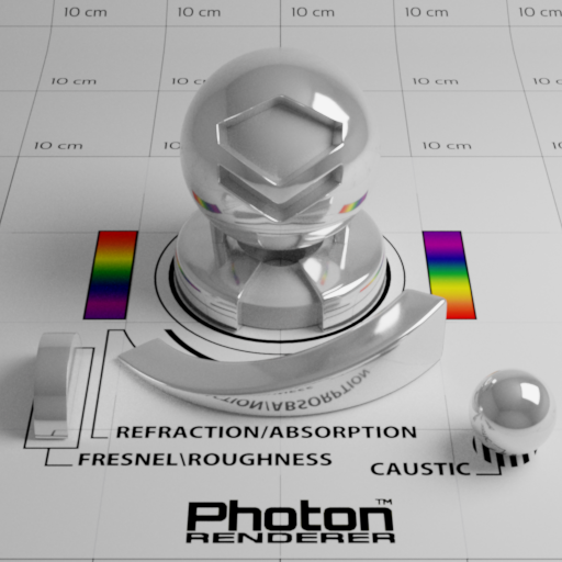
We could simulate some material that is not possible to exist in the real world. One common genre is the idealization of surface roughness, where perfectly smooth interface is modeled. Ideal substance makes the visualization of these kinds of material possible, which is of great interest for both theoretical and practical usages.
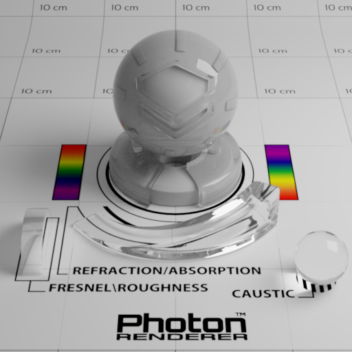
Photon also supports tinting reflectance and transmittance with user specified values. Note that this is not physically correct since color of dielectrics come from internal volume absorption, not from interfaces. This feature is implemented for performance and artistic reasons only.
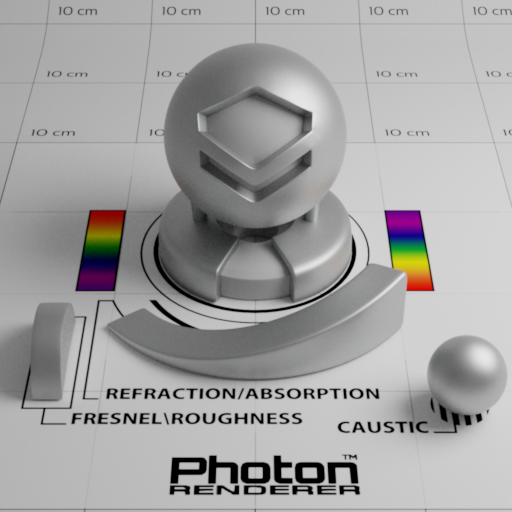
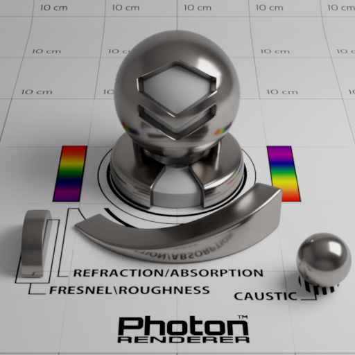
Abraded Opaque
Sometimes a tweakable roughness value can be useful for opaque materials. A popular BRDF model that allows this is Cook-Torrance microfacet BRDF. For normal distribution function, we use the GGX model (or Trowbridge-Reitz model) since it has been shown that it matches experimental data pretty well. A good reference of microfacet models is the paper (“Microfacet Models for Refraction through Rough Surfaces”, EGSR07) written by Walter et al. My implementation is capable of using both exact and approximated (see “Reflections and Refractions in Ray Tracing” by Bram de Greve) versions of Fresnel equation. In the case of exact Fresnel equation, measured spectral index of refraction (IoR) can be used (complex IoR is also supported). The site https://refractiveindex.info/ has a good collection of measured IoR data.
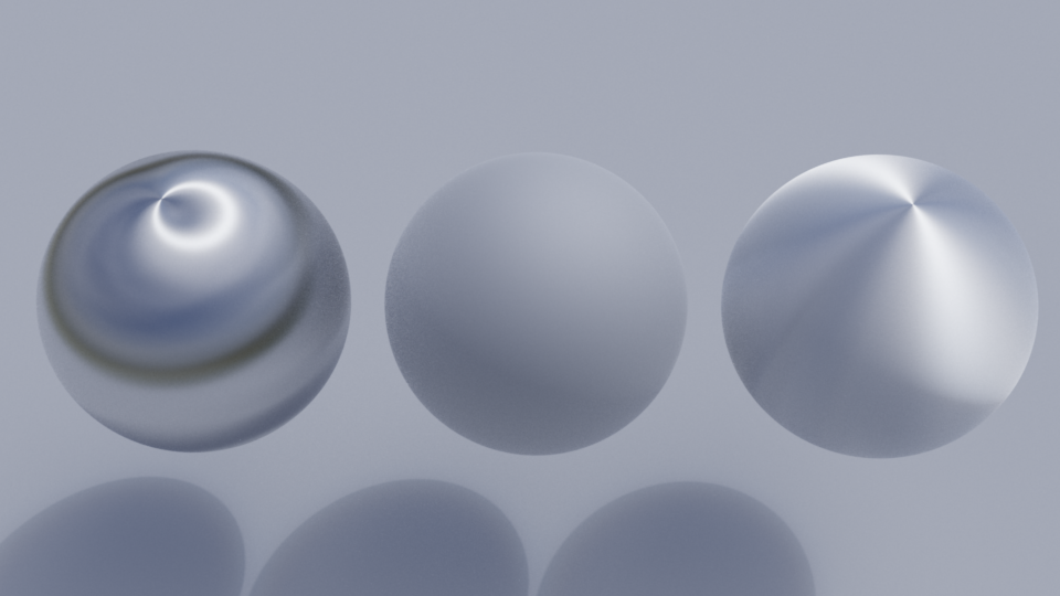
Anisotropic variant of GGX distribution exists, which is described thoroughly in Disney’s course note at SIGGRAPH 2012 (“Physically-Based Shading at Disney”, Brent Burley, SIGGRAPH 2012). For anisotropic normal distribution function (NDF), I implemented the D_GTR variant with γ=2. A sharp edge of anisotropic materials is that they require a properly mapped UV coordinates across the mesh in order to form a local basis around the shading point, which is necessary for determining the value of NDF. Below is a render of anisotropic microfacet materials:
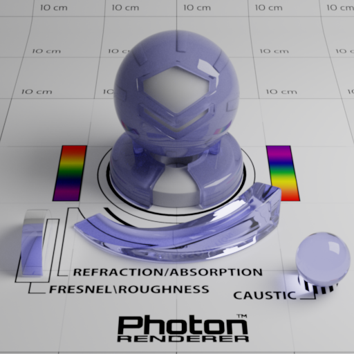
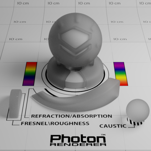
Abraded Translucent
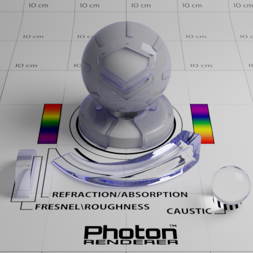
Since the aforementioned microfacet model is just a description of microgeometry, it can be applied to the case of transmission of light with some modifications. The most prominent change is that for each shading point we now need to trace two paths instead of one, for reflection and transmission, respectively. Much of the code for handling reflection can be reused, but not for transmission (it requires an additional BTDF). This is one of the reason why the abraded opaque and translucent materials do not share a common base class. Abraded translucent material is good at modeling frosted glass, and only single-bounce lighting inside the microgeometry is simulated currently (simulating multi-bounce lighting inside microgeometry has already been done. See “Multiple-Scattering Microfacet BSDFs with the Smith Model” by Heitz et al., SIGGRAPH 2016).
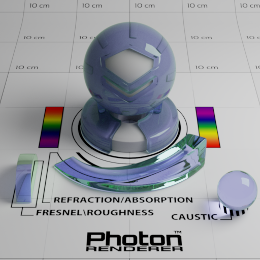
Binary Mixed Surface
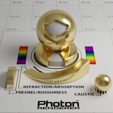
Being able to mix two different materials greatly increased the diversity of possible materials. The mixing process can be nested–a mixed material can participate in another mixing process just like ordinary materials. Some material appearances such as plastic and ceramic can be achieved easily by this model (though it may not be accurate), which is illustrated below:
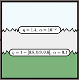
Layered Material
Layered material models prevalent in graphics community in recent years. Some great models exist, but each of them has non-negligible shortcomings. Solution by Jakob et al. (“A Comprehensive Framework for Rendering Layered Materials”, SIGGRAPH 2014) requires large memory space to store some BSDF, while model developed by Weidlich et al. (“Arbitrarily Layered Micro-Facet Surfaces”, GRAPHITE 2007) does not obey the law of energy conservation. In last year, a brilliant idea came from Laurent Belcour (“Efficient Rendering of Layered Materials using an Atomic Decomposition with Statistical Operators”, SIGGRAPH 2018) partially solved the problem. His solution is not exact, but is energy conserving, space efficient, and plays well with texture mapping. My implementation follows Belcour’s closely, with some refactoring and improvements on numerical robustness.
Note that the mug material uses the same parameters taken from the teaser image of Belcour’s paper:
Please note that a later research (“Position-Free Monte Carlo Simulation for Arbitrary Layered BSDFs”, Guo et al., SIGGRAPH Asia 2018) achieved unbiased rendering of layered materials, with all the benefits that Belcour’s model had.